
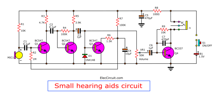
Competition Circuit Diagram This circuit is a simple hearing aid circuit which is powered with 1.5V battery the working of this circuit is mentioned below. The electret microphone picks up sound waves and converts them into a small voltage signal. Transistor T1 BC547 amplifies this weak signal. Resistor R3 330k and capacitor C2 10uF set the bias point for T1.
Ultra-High Fidelity High Power Amplifier Reference Design; Speach Amplifier; DC-Coupled Audio Amplifier; A Low Power Wireless Audio Power Amplifier; Here is an inexpensive hearing aid circuit that uses just four transistors and a few passive components. Circuit diagram. Parts: R1 = 2.2K R2 = 680K R3 = 3.3k R4 = 220K R5 = 1.5K

ElectroSchematics.com Circuit Diagram
In a hearing aid circuit, Solder the Lm386 Amplifier to the circuit board or place it on the breadboard. Follow the pin configuration provided in the amplifier's datasheet. you can create a customized hearing aid that suits your specific needs. However, it is essential to remember that a DIY hearing aid should not be considered a
With the right guidance and knowledge, you can take charge of your hearing health and create a device that works well for you. So, don't be afraid to dive in and explore the possibilities of hearing aid engineering! A Low Cost Hearing Aid Circuit Diagram. Speach Amplifier Circuit Diagram And Instructions. The making of the hearing aid is also very simple and would not take more than an hour. The output of the device is a little cracky due to the crude op amp used but for the cost it is made (that is less than 1$) the device is very appreciable. Low-cost hearing aid circuit. The circuit can be easily assembled on a small, general-purpose PCB or a Vero board. It operates off a 3V DC supply. For this, you may use two small 1.5V cells. Keep switch S to 'off' state when the circuit is not in use. To increase the sensitivity of the condenser microphone, house it inside a small tube.
Hearing Aid Circuit: An Easy and Affordable DIY Project Circuit Diagram
The audio output of this aid circuit is 10 to 15 mW and the quiescent current drain is below 1 mA. The circuit can be easily assembled on a veroboard. For easy assembling and maintenance, use an 8-pin DIP IC socket for TDA2822M. Schematic of Hearing Aid Circuit The LM386 is a low-voltage audio power amplifier IC that is perfect for this project. the external components used. The LM386 is easy to use and requires minimal external components, making it ideal for a simple hearing aid circuit. and a little bit of technical know-how, you can create a basic hearing aid that can help improve your or
